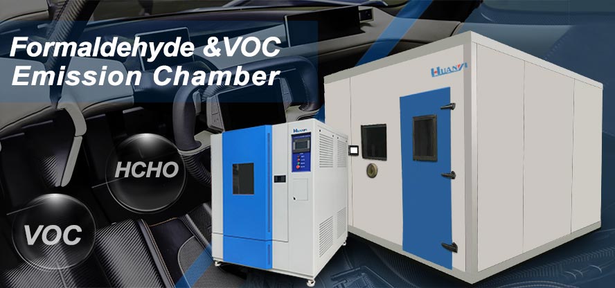
VOC emission test chamber Apparatus and Facilities
3.8.4 Apparatus and Facilities: The apparatus and facilities shall be constructed to maintain the test specimen at the specified conditions within a non-contaminating and low sorption environment.
3.8.4.1 Clean air supply and flow control: A clean air generator or high purity air cylinders shall be used to supply pressurized clean, dry air. The flow rate of the supply air to a chamber shall be regulated and monitored with electronic mass flow controllers (MFCs), or equivalent, with an accuracy of±2 % of full scale, or better, and capable of continuously maintaining the flow within±5 % of the specified value. The supply air flow rate shall be maintained within±5 % of the specified value throughout the 96-hr test. MFCs shall be calibrated periodically according to the Laboratory's quality management system. At a minimum, flow measurement devices shall be calibrated on an annual basis against NIST traceable standards. As the humidity of the supply air is maintained by mixing dry and saturated gas streams, two mass flow controllers may be required per chamber (i.e., one for the dry stream and one for the wet stream). The dry and wet streams shall be mixed before the supply air enters the chamber.
3.8.4.2 Chamber and materials: The chamber volume shall be between 50 L and 1 m'. The chamber shall be constructed of stainless steel. Stainless steel chambers shall have electro-polished, or equivalent, interior surfaces. Either rectangular or cylindrical shapes are acceptable. The chamber shall be designed as a single-pass system without recirculation of chamber air. The chamber shall be operated at a slight positive pressure relative to the room to prevent the entrainment of room air. The chamber inlet and exhaust shalll be positioned and designed to ensure complete mix ing of chamber air.
The chamber lid/door shall have a non-contaminating, non-sorbing gasket and a closure mechanism to create an airtight seal. Other materials introduced into to the chamber (e.g.. racks and probes) shall be constructed of non-contaminating materials such as stainless steel.
3.8.4.3 Background concentrations in the empty chamber ventilated at 1.0 air changes per hour shall not exceed 2 μg m'3 for any individual VOC, and 25μg m3 for TVOC.
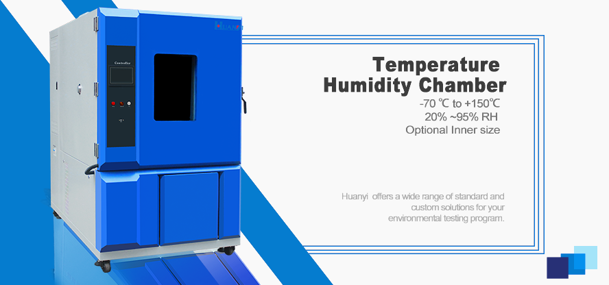
3.8.4.4 Temperature and humidity control: The temperature of the chamber shall be
maintained within the range of 23±1°C for at least 90% time throughout the 96-hr test, and within range during sampling and for three air changes prior to sampling. In no case shall the temperature range exceed 23±2°C. All surfaces of the chamber shall be held at the same temperature so that the temperature inside the chamber is uniform.
Typically, this is accomplished by placing the chamber inside a temperature-controlled environment such as an incubator or a dedicated room. The humidity of the chamber air shall be maintained within the range of 50±5% RH for at least 90% time throughout the 96-h test, and within range during sampling and for three air changes prior to sampling. In no case shall the relative humidity range exceed 50±10% RH. As wet products (e.g.. water-based paints) will have 10 days of prior conditioning, the RH of the chamber air should be nearly equivalent to the RH of the inlet air. Thus, the humidity can be established by controlling the humidity of the inlet air. Generally, this is accomplished by mixing equivalent flows of dry and water saturated air streams.
Water used in bubblers to saturate gas streams shall be free of organic solvents and contaminants (i.e., HPLC grade or equivalent).
3.8.4.5 Monitoring and data acquisition: The temperature and relative humidity for a chamber shall be measured continuously and independently of the systems for controlling temperature and humidity. The measurements shall be made inside the chamber or immediately at the chamber exhaust using electronic probes. The probes shall be calibrated periodically according to the laboratory' s quality management system. At a minimum, these probes shall be calibrated on an annual basis against NIST traceable standards. Chamber inlet flow rates, temperature and relative humidity shall be recorded using a computer-based data acquisition system. At a minimum, these data shall be recorded at 5-minute intervals.


