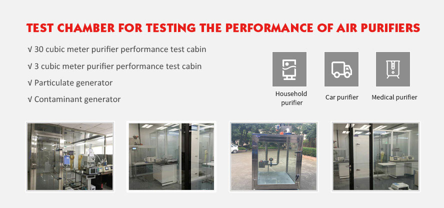
30m³ Air Cleaner Test chamber construction, placement and cleaning methods
Schematic diagram for 30m3 air cleaner test chamber

Descriptions:
1 — Stirring fan; 2 — Circulating fan;
3 — Test prototype; 4 — Pollutant detection device;
5 — Pollutant generation device; 6 — Air filter;
7 — Air supply valve of test chamber; 8 — Air supply of constant temperature and constant humidity air conditioner (air supply in air exhaust) for test chamber;
9 — Air duct reversing valve (for converting 10 — Air return of constant temperature and constant humidity
the air return paths 10 and 11); air conditioner for test chamber;
11 — Test chamber exhausting air to the 12 — Exhaust valve of test chamber;
outside (including air filter);
13 — Door of test chamber; 14 — Air inlet of constant temperature air conditioner for outer chamber;
15 — Air return opening of constant temperature 16 — Door of outer chamber;
17 — Sampling outlet and sample sending opening of test 18 — Regulated power supply.
Placement of 30m3 purifier CADR test chamber:
Central position: ground type (on the ground), desktop type (on 700mm tabletop), wall mounted type (1800 mm from lower edge to ground), ceiling type (on 700mm tabletop).
If not specified, the placement type is classified according to the height of the air outlet: place the test prototype on the tabletop if the height of the air outlet is less than 700 mm; place the test prototype on the ground if the height of the air outlet is more than or equal to 700 mm.
Note: If the cleaning function is the auxiliary function, for air conditioner, the dehumidifier, the fresh air unit etc., it shall be tested in complete-product level, however, the relevant components with the cleaning properties are only required to be started, and other components are not required to be started.
Mop the floor with the wet mop after use for 5 days.


